
Solar inverter housing
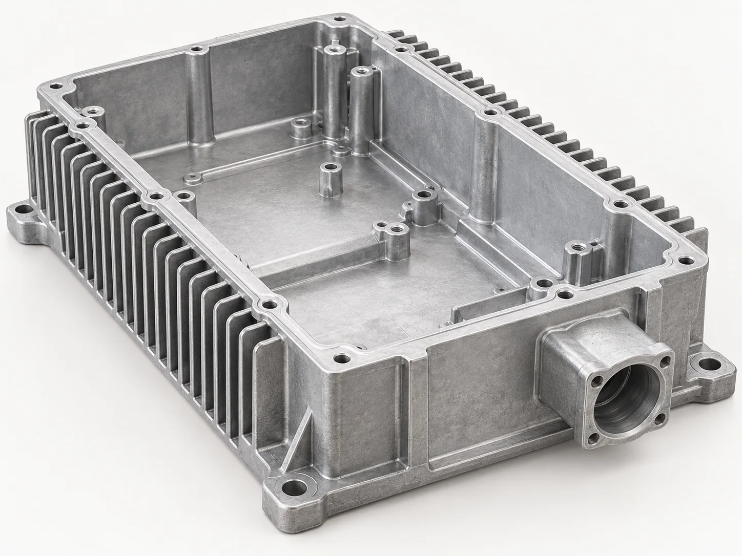
Enclosure cavity, cooling fins and cable entry.
ENERGY & POWER TOOLING
Custom aluminum molds for inverter, charging module and power equipment components. Share clear part drawings or an assessable sample to discuss your mold project.
Mold-only service · One mold set welcome
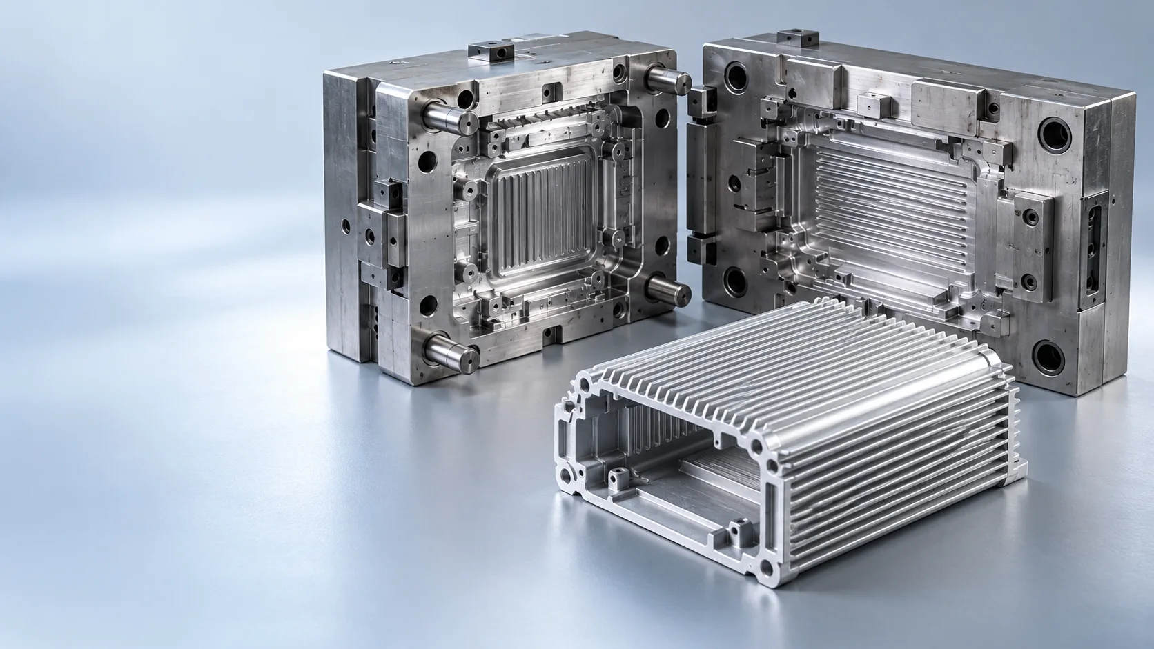
Custom mold toolingFor your defined aluminum part
Drawings or sampleThe basis for a formal quote
Two approval pointsDesign, then trial samples
POWER EQUIPMENT APPLICATIONS
Nine different aluminum component types show the range of shapes and interfaces that can start a mold discussion. Each image is illustrative; project suitability depends on your part reference.
Different shapes for inverter and supply equipment.
Enclosure cavity, cooling fins and cable entry.
Upright body with a front opening and rear fins.
Compact ribbed body with side openings.
Specify each interface against the actual equipment design.
Compartmented body with mounting and port features.
Open cavity, mating rim and cable-entry bosses.
Small cover with fasteners and connector openings.
Geometry and receiving requirements need project review.
Exposed fins on a thick mounting base.
Broad floor with supports and a reinforced edge.
Open structural frame with bolt locations.
Generated application illustrations, not delivered customer cases. These are component ideas for mold discussion; feasibility is reviewed against your actual drawings or assessable sample.
DEFINE THE PART, NOT JUST THE PRODUCT
Enclosure shape alone does not define a mold. Mark the actual interfaces and current part revision before requesting a formal quote.
Show the space reserved for the customer-supplied assembly.
Identify openings, locations and any later machining.
Mark how the casting attaches to the surrounding product.
Identify the lid interface and relevant surfaces.
Include fins, ribs and visible surfaces in the part drawing.
Thermal, electrical, environmental and safety requirements are project inputs to discuss. The mold service does not by itself guarantee a finished product rating or certification.
PREPARE YOUR MOLD INQUIRY
Upload a STEP/STP model or dimensioned 2D drawing for the current version. An assessable physical sample is another route. Include the intended assembly, important interfaces and where the mold will be used.
Upload Product DrawingsFROM DRAWING TO MOLD HANDOVER
Customer decisions are built into the process before mold manufacturing and before final shipment.
Upload clear 2D/3D drawings or describe an assessable sample.
Confirm the mold scope, project terms and payment.
Approve the 3D mold design before manufacturing begins.
Review mailed trial samples against agreed part requirements.
We dispatch the finished mold after your sample approval.
Typical mold production is about 30–40 days from payment, subject to scope and approval timing. This is not a guaranteed arrival date.
See the Full Mold ProcessBEFORE YOUR INQUIRY
No. The current service is a custom aluminum die casting mold for an agreed component. We do not supply finished electrical products or ongoing cast-part production.
No. Share the relevant product requirements for project-specific review. The mold and illustrative component images do not establish thermal results, electrical safety, environmental protection or certification.
Provide clear 2D or 3D part drawings, or an assessable physical sample. Identify the current revision, key interfaces and any requirements that affect the component.
Yes. One mold set is welcome. We confirm the actual scope, quotation and delivery terms with you before a project begins.
YOUR NEXT MOLD PROJECT
Upload your current part drawings or describe an assessable sample. We will review the mold scope and follow up through your chosen contact details.