
Rotary actuator housing
A compact body around a rotary output and mounting interface.
INDUSTRIAL AUTOMATION TOOLING
From actuator housings to sensor enclosures and machine mounts, we coordinate custom molds for your defined aluminum part. Share clear 2D/3D drawings or an assessable sample to start a quotation. One mold set is welcome.
Mold-only service · One mold set welcome
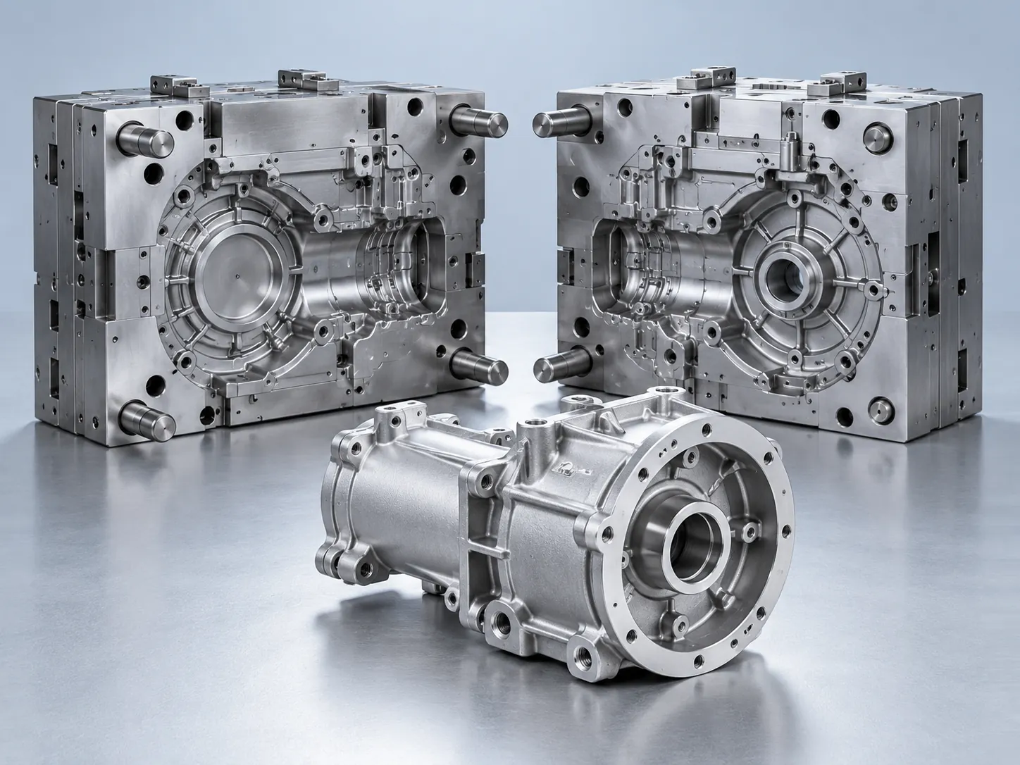
Component-specific moldFor your defined aluminum part
Drawings or sampleThe basis for a formal quote
Two approval pointsDesign, then trial samples
AUTOMATION COMPONENT APPLICATIONS
These distinct examples show the types of aluminum components a custom die casting mold can be discussed for. They are generated illustrations, not delivered customer projects.
Housings and structures around controlled movement.
A compact body around a rotary output and mounting interface.
A structural body for an end effector assembly.
An end cover with mounting and mating features.
Enclosures where openings and mating surfaces matter.
A small housing with connection and fixing points.
A camera enclosure form with lens and assembly interfaces.
A protective body around a shaft-sensing assembly.
Supports and covers that must fit the surrounding equipment.
A compact mechanical interface for tooling attachment.
A rigid support with defined fastener and locating faces.
A protective cover with a defined mating rim and openings.
Generated application illustrations, not delivered customer cases. Each part and its suitability for a die casting mold must be reviewed against your drawings or assessable sample.
DEFINE THE PART IN ITS ASSEMBLY
An equipment photo gives context. The part drawing defines what the mold must make and what may need later machining.
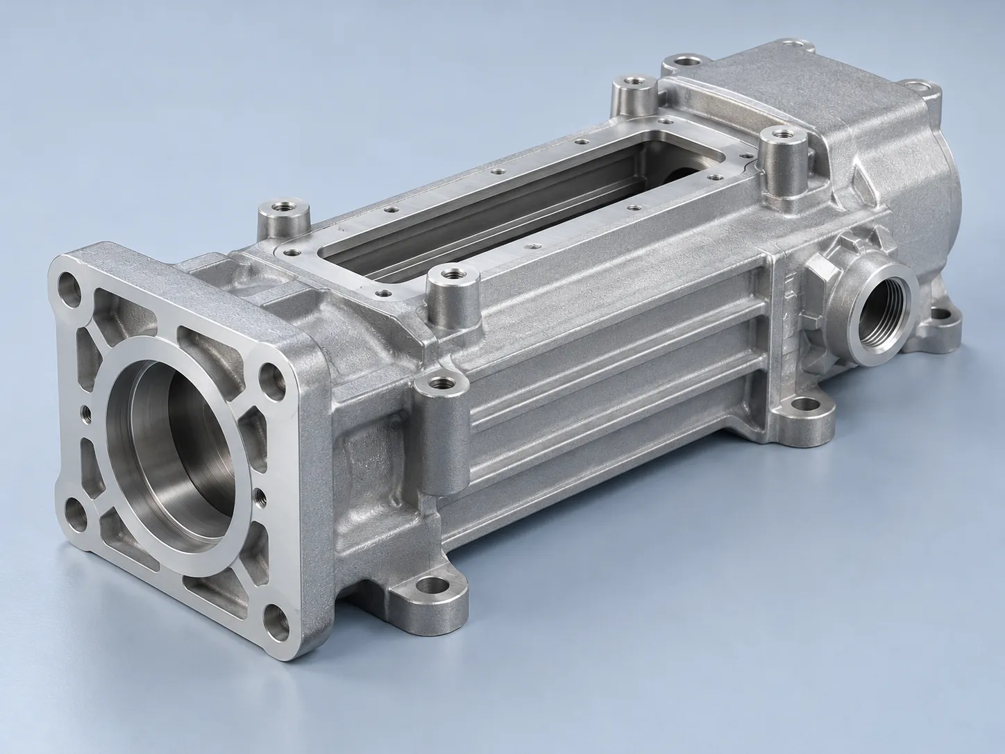
Show the surfaces and hole locations that connect the casting to the machine.
Mark the space needed around nearby moving parts.
Identify openings and the parts that mate with them.
Call out bores, threads or faces that need a separate finishing step.
Loads, vibration, sealing and operating life are project requirements to discuss. A mold illustration does not establish finished-equipment performance or certification.
VERSION CONTROL
If the same component has multiple versions, mark what changes and identify the version to quote first. Several drawings do not automatically mean one mold scope.
| Reference to send | Difference to identify | What we confirm |
|---|---|---|
| Current drawing | Revision and any recent changes | The exact part version to quote |
| Alternative version | Mounting, opening or envelope changes | Whether separate tooling needs review |
| Physical sample | Repairs or planned modifications | A usable quotation reference |
Comparison checklist only; it does not describe an actual customer project or promise that versions share a mold.
PREPARE YOUR MOLD INQUIRY
Upload a STEP/STP model or clear dimensioned 2D drawing, or tell us about an assessable physical sample. Include the intended machine, mating parts and the revision you want quoted.
Upload Product DrawingsFROM PART REFERENCE TO MOLD HANDOVER
Your confirmation comes before mold manufacturing and again before final mold shipment.
Share current 2D/3D drawings or an assessable physical sample.
Agree the part revision, mold scope and project terms.
Review the 3D mold design before manufacturing.
Test mailed samples against the agreed part requirements.
We send the finished mold after your sample approval.
Typical mold production is about 30–40 days from payment, subject to scope and approval timing. This is not a guaranteed arrival date.
See the Full Mold ProcessBEFORE YOUR INQUIRY
A physical sample can be reviewed. Explain repairs, modifications and differences from the intended product before a quotation reference is agreed.
No. The website offer concerns a custom aluminum die casting mold for your component. Complete machine design and system integration are outside that scope.
List each variant for review. The quotation must identify the drawings and mold scope it includes rather than assuming all versions are covered.
Share clear 2D or 3D drawings for the aluminum component, or an assessable physical sample. Identify the current version, mounting interfaces and intended use so we can review the mold scope.
YOUR NEXT MOLD PROJECT
Tell us what you want to make, what information you have, and when you plan to purchase. We will review your inquiry and follow up by email or your permitted contact channel.