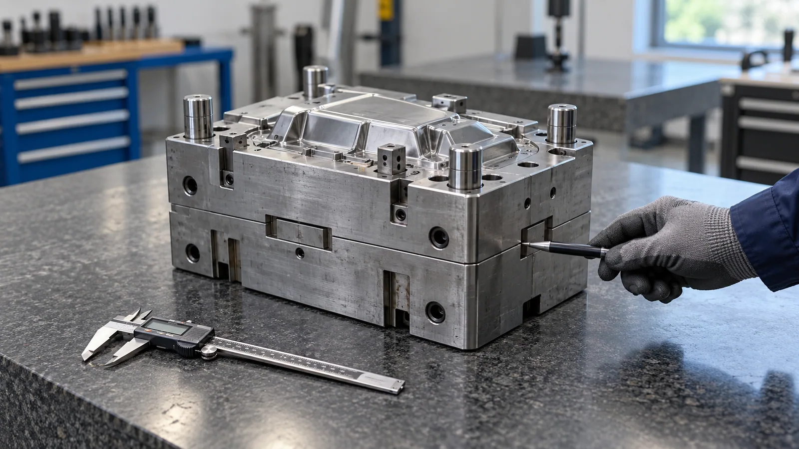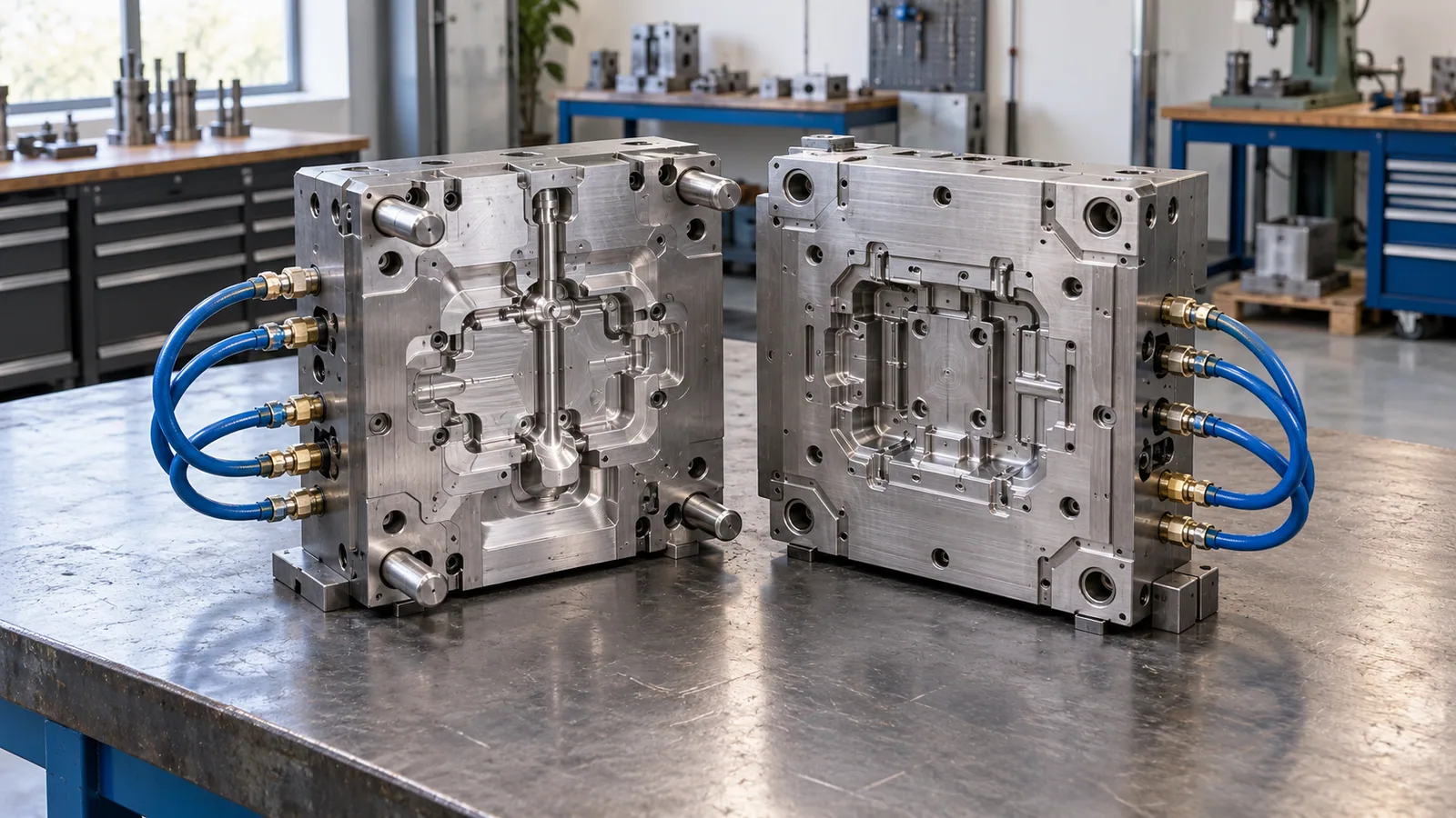
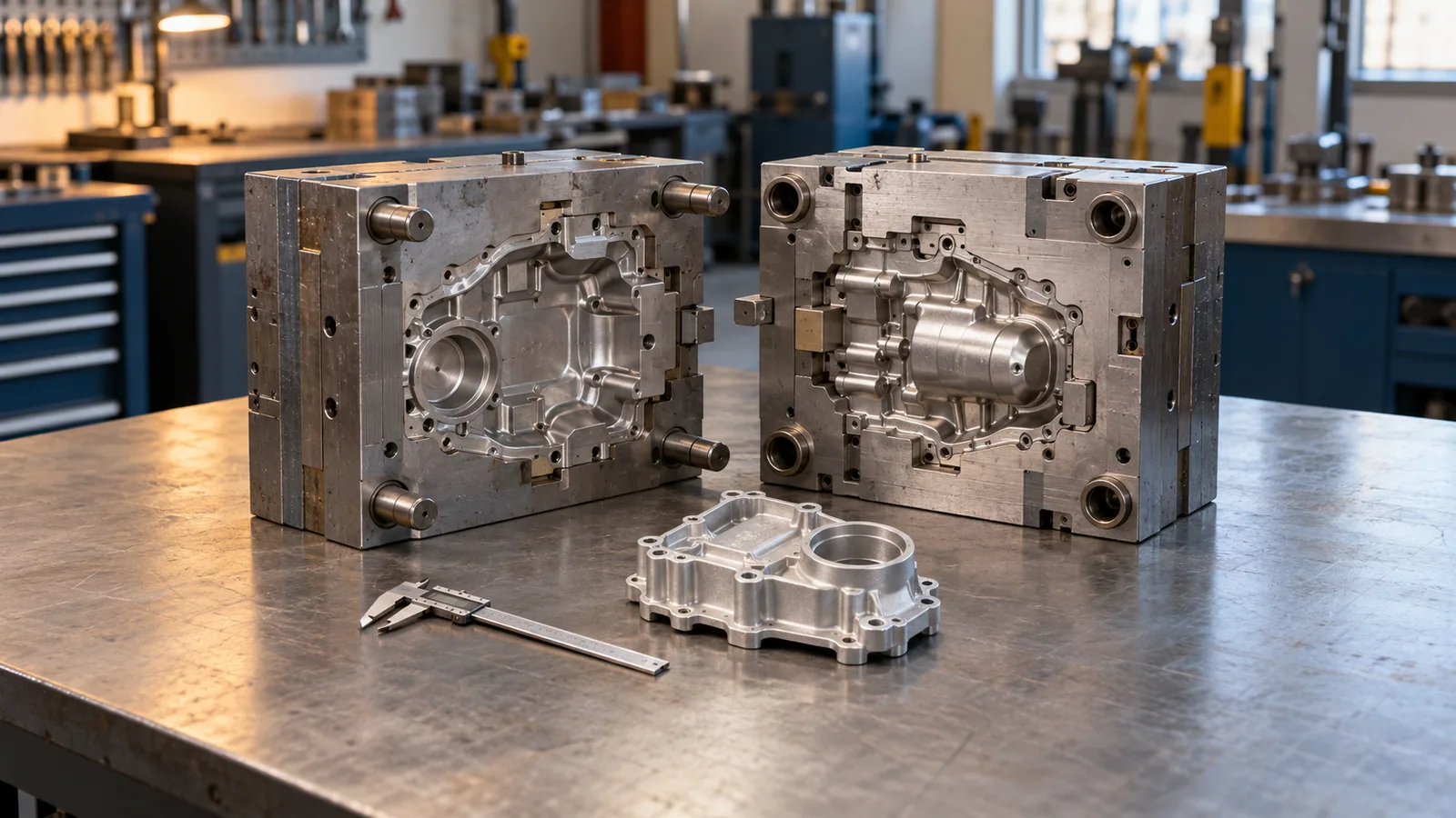
An aluminum die casting mold is more than two blocks of steel shaped like a part. The closed die creates the cavity; a runner and gate deliver metal; vents provide an exit for displaced air; temperature-control passages manage heat; and ejector pins release the casting after the die opens. Movable cores may be needed when a feature cannot be formed in the main opening direction. Understanding these elements helps a buyer read a proposed 3D mold design and ask useful questions without taking over the tooling engineer's job. NADCA: Die Design and Construction FAQ
01 / 08
Start with the closed die
In a typical high-pressure die casting tool, the cover half is stationary and the ejector half moves with the machine. Their shaped faces meet at the parting surface and enclose the casting cavity. The cover side includes an opening for metal entry; runners and gates commonly lie on the ejector side, although the layout is engineered for the particular tool. Locking and alignment features help the halves meet repeatedly. NADCA: Die Design and Construction FAQ
The cavity is not simply an inverted finished product. It must account for how the component will be formed, separated, released and, if necessary, finished later. A visible seam on the casting traces the parting line where die sections meet. Choosing that line early affects which side forms a face, where connected runners and overflows can be removed, and whether a critical dimension crosses the split. NADCA: Parting Line
For a housing, mark the gasket seat, bearing location, mounting points and surfaces visible in the final assembly. The drawing should distinguish as-cast geometry from a precision surface that will be machined later. The tooling team decides the die layout; the customer confirms which product features and interfaces must be preserved.
ILLUSTRATIVE MOLD ANATOMY
02 / 08
Follow the metal and the displaced air
For an aluminum cold-chamber process, metal reaches the die through the injection system. A runner conducts it toward the cavity and a gate is the inlet into the part shape. The gate is connected to the casting and will be removed after the shot. Its position should therefore be considered alongside part filling and the acceptability of a gate mark on a functional or visible face. NADCA: Die Design and Construction FAQ · NADCA: Gating and Process Planning Series
The incoming metal displaces air already inside the die. Vents provide an exit route. Overflow cavities can receive metal and help manage flow at selected locations; a NADCA design case shows overflow tabs and a vent line positioned opposite a gate for a particular heat-sink block. That example is a demonstration of layout reasoning, not a template for every component. NADCA: Die Design FAQ · NADCA: Overflow Design Case
These features are designed as a connected system. A visually neat cavity with no credible metal and air paths is not a complete mold proposal. Conversely, a single photograph of a pore cannot establish that a vent is the cause: process conditions, metal handling, geometry and the die must all be considered.
| Element | What it does | A useful design-review question |
|---|---|---|
| Runner | Carries metal toward the cavity | Where does the proposed flow path approach the part? |
| Gate | Introduces metal into the cavity | Where will the connection and later removal mark sit? |
| Vent | Gives displaced air an exit path | Which regions are expected to fill last? |
| Overflow | Receives metal at a planned location | Where is it attached, and how will it be removed? |
03 / 08
Manage heat without weakening the working steel
Die steel repeatedly receives heat from molten metal and gives it up between shots. Water or oil passages in the die help remove heat. NADCA identifies their location as important to thermal balance. A passage cannot simply be placed at equal spacing everywhere: cavity geometry, steel support, moving parts and access for maintenance constrain its route. NADCA: Die Design FAQ
In an illustrative housing with a deep bearing boss and a broad thin flange, those regions impose different thermal demands. The engineer may adjust local temperature control and the filling approach together. This does not mean that one visible thick feature proves a cooling defect, or that a generic channel layout will produce the required casting. Trial observations and the actual process setting are needed to evaluate the result.
When looking at a 3D mold model, ask whether the temperature-control arrangement has been considered around deep features, inserts and slides. You need not approve channel diameters or promise a cycle time. You do need to flag any part feature whose fit, sealing or appearance may be affected by a proposed change to the casting geometry.
04 / 08
Release the casting after opening
The die must separate without trapping the solidified component. Ejector pins push it from the ejector half. Their locations and combined action matter because uneven release can distort or damage a part. A slide or movable core may form a side hole or recess that blocks straight withdrawal; it retracts in another direction before ejection. Whether such a mechanism is needed depends on the chosen opening direction and the exact part shape. NADCA: Die Design FAQ · NADCA: Slides for Internal Features
Draft, the slight taper on a face parallel to withdrawal, also helps release. It is evaluated feature by feature rather than copied as one angle across all walls. Deep internal faces and outside walls can behave differently. For a closer review of those decisions, see Parting Lines, Draft and Undercuts. NADCA: Draft
The casting often leaves the die attached to gates and other extra metal that must be trimmed. The sample the customer tests should be described clearly: which features are as-cast, which have been trimmed, and which, if any, were finished for the agreed trial. That distinction prevents a polished sample from hiding an unresolved tooling question.
05 / 08
Illustrative example: a small aluminum motor housing
Imagine a housing with an internal cavity, a bearing seat, four mounting bosses and a side opening. The product model defines what the part must do. The mold model needs a credible way to form and release it.
- The cover and ejector halves form the outer wall and internal cavity. The proposed parting line is checked against the gasket face and mounting pattern.
- A runner and gate are positioned for the selected filling strategy. The customer identifies surfaces where a gate-removal mark would be unacceptable.
- Vents and overflows are considered where displaced air and late flow may need an exit. Their exact geometry depends on the full filling analysis.
- Temperature-control passages are arranged around the working steel and moving components; their design is assessed with the expected thermal load.
- The side opening is checked against the main pull direction. It may call for a moving core, a changed part feature or an agreed later operation.
- Ejector pins release the casting. The bearing seat is identified as as-cast or finished, with its functional requirement recorded.
This is an illustrative example, not a customer project, approved die layout or promise of a particular casting result. It shows why a 3D mold proposal should be reviewed as a system, not as a set of isolated metal blocks.
06 / 08
What to confirm before mold manufacture
| Customer confirms | Tooling team evaluates |
|---|---|
| Correct product drawing and 3D revision | Die split, cavity and insert arrangement |
| Fit, sealing, bearing, mounting and visible faces | Runner, gate, vent and overflow layout |
| Which surfaces may be finished later | Temperature control, slides and ejection |
| Any geometry change affecting function or assembly | Trial approach and technical corrections |
The customer should check the product geometry shown in the proposed 3D design and respond to specific questions. The tooling team remains responsible for engineering the mold. A sent model is not an approval: record the reviewed revision and resolve material differences before an explicit sign-off. See How Mold Design Review Works.
Common mistakes include treating a rendered image as a complete tooling drawing, overlooking a side opening that needs a different release path, and assuming that a precision bore shown on a finished product model will emerge from the die at its final condition. Each is caught more easily by comparing the current drawing revision with a model that shows the split, moving features and intended finishing.
07 / 08
Frequently asked questions
Is the cover half always responsible for the visible outside face?
No universal rule assigns every visible face to one half. The split is chosen for the part and the casting process. NADCA notes that cosmetic surfaces are often placed on the cover side, but the actual proposal must be checked against functional surfaces, release and trimming. NADCA: Parting Line
Are cooling channels part of the product drawing?
They are internal die features, not part of the casting itself. A customer can ask how heat management is addressed without specifying the engineering dimensions of each passage. NADCA: Die Design FAQ
Does a mold photo prove the proposed part will work?
No. A photo can show a tool form, but it cannot confirm the current drawing revision, hidden moving features or the tested fit of the resulting sample. Check the identified 3D design and then assess the trial samples against the agreed product requirements.
08 / 08
A practical next step
Open the latest 2D drawing or 3D part file and mark the faces that cannot move or change. During the mold review, ask the team to show the parting line, metal entry and air exit, temperature-control concept, side actions and release direction on the same design. Confirm the exact revision before manufacturing begins. If you are preparing a new custom mold, you can share the part drawing or describe a physical sample.
Further reading
Technical references used to check this article:
Have a component in mind?
Share a clear 2D or 3D drawing, or tell us about a physical sample. We discuss the mold scope for your part.
Start a mold inquiry