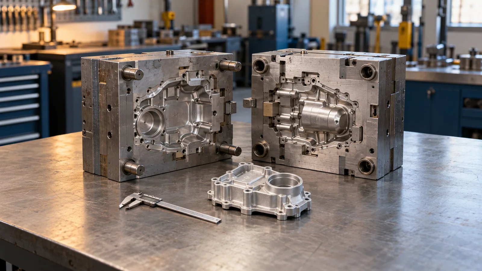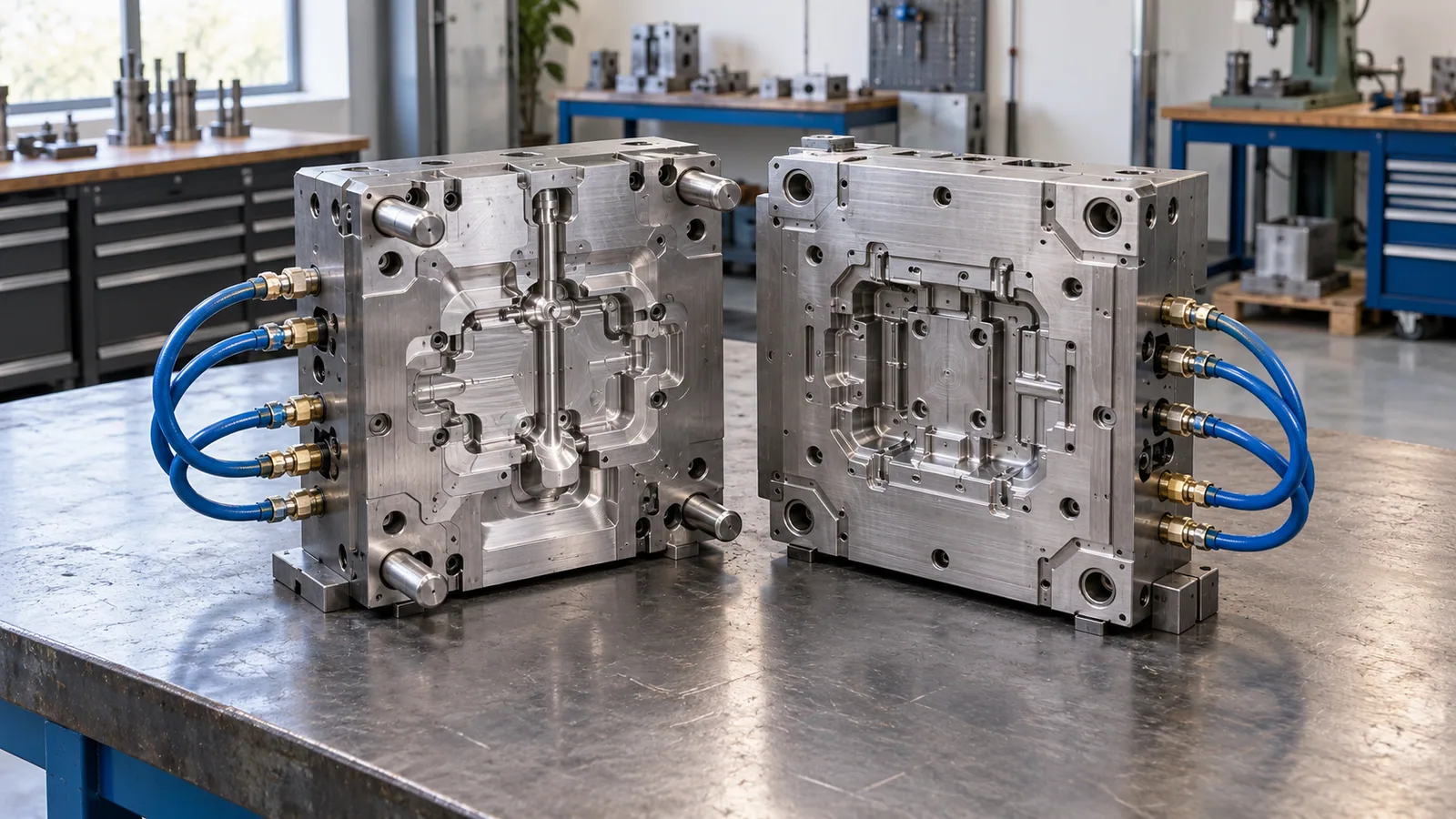
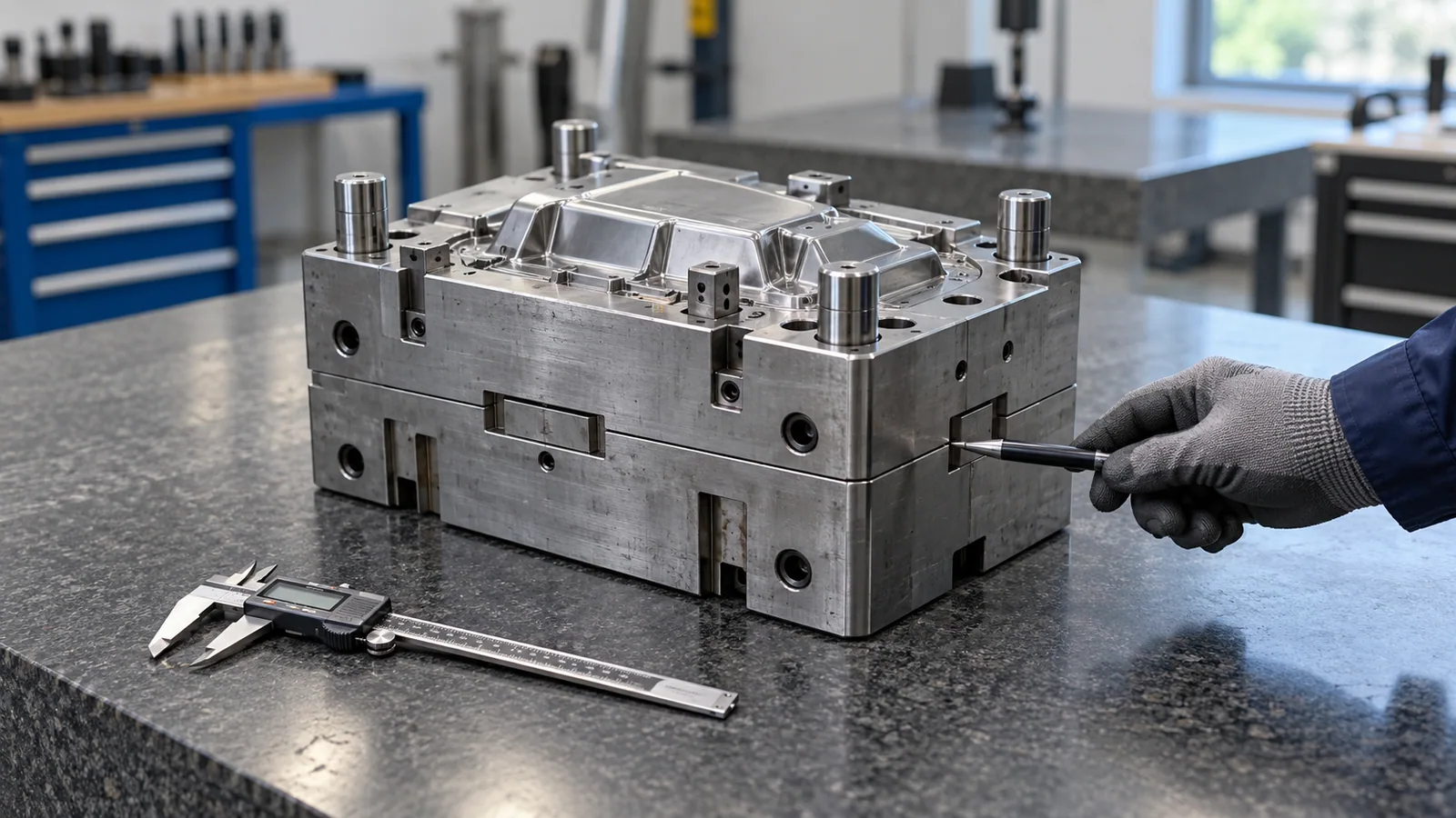
A die casting mold must close around a cavity, open again and release the aluminum part. Three design choices control much of that sequence: where the two die halves meet, how the part's walls clear the steel as it opens, and whether any feature traps the part in the tool. These are the parting line, draft and undercuts.
The right answer depends on the actual component. A sealing face, side hole or deep boss can change the preferred layout. Use the checks below to review the proposed 3D design against your product requirements before approving the mold. The tooling team still needs to determine the final engineering solution for the agreed part and casting conditions. NADCA: Parting Line · NADCA: Draft
01 / 09
Start with the opening direction
Imagine an open-top aluminum motor housing. Its interior cavity, mounting bosses and outer walls must be formed by steel that can move away after the casting solidifies. First identify the main direction in which the cover and ejector halves separate. Then look at every surface and opening relative to that direction. A vertical wall, a side-facing hole and a lip projecting inward do not release in the same way.
This simple view prevents a common mistake: assessing a feature only on the finished part. The 3D model may look correct while the steel needed to form a feature cannot withdraw along the planned opening path. Some holes and internal features can be formed with movable slides or cores, which retract before ejection. Whether that is the best approach depends on the part's function and the complete die layout. NADCA: Die Design and Construction FAQ · NADCA: Slides for Internal Features
ILLUSTRATIVE DESIGN REVIEW
02 / 09
Parting line: where the halves meet
The parting line is the trace left on the casting where the two die halves meet. Its position determines which areas are formed by the cover half and which by the ejector half. It also influences where flash may form and where gates, overflows and vents connect to the casting. That makes it a functional and manufacturing decision, rather than a line to hide after the design is complete. NADCA: Parting Line
For a housing, begin by marking the faces that matter most: a gasket seat, a bearing location, an exterior surface that remains visible, and any face that must align closely with a mating component. Ask whether the proposed parting trace crosses one of them. A visible seam may be acceptable on a noncritical outside edge; the same seam across a sealing or locating face can require closer review or later finishing. The answer is specific to the drawing and its acceptance requirements.
Dimensions measured across the parting line may be affected differently from dimensions formed within one die half. NADCA advises keeping critical dimensions within one die half where possible to reduce the additional variation associated with the split. This is a design consideration, not a guarantee that moving the line alone will meet a particular tolerance. NADCA: Parting Line
When reviewing the 3D mold, ask for the parting trace to be visible on the casting model, not only on the mold blocks. Confirm the planned treatment of gates and any flash on surfaces that affect assembly, appearance or testing. If a critical face must cross the split, record the requirement and the proposed way to check it on the trial samples.
03 / 09
Draft: how a wall clears the steel
Draft is a small taper on a surface that would otherwise run parallel to the die's withdrawal direction. It gives the casting clearance as the steel moves away. The required taper is not one universal angle: NADCA notes that it varies with the type and depth of the surface and the alloy. Internal walls and cored holes can need different treatment from outer walls because the cooling casting grips the steel differently. NADCA: Draft
Look beyond the large outer walls. Deep pockets, ribs, bosses, lettering and cored holes also need to be examined in the chosen pull direction. In a 3D review, a color-coded draft analysis can make surfaces with insufficient or reverse draft easier to identify. The color result is only a screening view: the team must still evaluate the feature's geometry, surface requirement and ejection arrangement. NADCA: Draft · NADCA: Holes and Windows
Suppose a motor housing needs a nearly straight bore for a bearing. Do not simply remove draft from the CAD model and assume the mold can release it. Mark the bore as a functional feature, its required finished condition and the permitted machining allowance, if any. The technical team can then evaluate the core, release and finishing strategy for that project. A cast hole and a finished precision bore are different requirements; the drawing should make that distinction clear. NADCA: CAD Feature Order
04 / 09
Undercuts: when the main opening path is blocked
An undercut is a feature that cannot be released by simply separating the two main halves in the chosen direction. A side-facing connector opening, inward-facing lip or lateral recess may create one. Changing the opening direction can sometimes remove one undercut while creating another elsewhere, so the complete part must be reviewed rather than one feature in isolation.
Movable slides or cores can form features that the main halves cannot release directly. In NADCA's illustrated die casting case, movable slides form internal geometry and access holes, then retract before the casting is removed. Such movement adds an interface and a sequence that must be designed, aligned and maintained. It can be appropriate when the feature is essential; it is not automatically the best answer for every side hole. NADCA: Slides for Internal Features
The following are design routes to discuss, not interchangeable promises:
| Route | When it may be considered | What to check before choosing it |
|---|---|---|
| Keep the feature and use a movable core or slide | The side feature is necessary in the as-cast geometry | Withdrawal direction, space in the tool, parting/flash at the moving interface and the approved feature dimensions |
| Change the part geometry or opening concept | The feature can move, open to an edge or change shape without losing function | Assembly fit, sealing, appearance and whether another surface becomes difficult to release |
| Form a simpler cast feature and finish it later | A precise hole or face needs a separate finishing operation | Which geometry is as-cast, which is finished, and how the finished feature is located and inspected |
The last route is a product and tooling design discussion. If the finished part depends on later machining, distinguish that requirement from what the mold forms as-cast. The mold quotation should state the agreed tooling scope clearly.
05 / 09
Worked example: a motor housing with a side opening
Illustrative example — not a customer case. Consider a small aluminum housing with an open front, a flat mounting rim, two internal bosses and a side opening for a cable connector. The customer provides a 3D part model and identifies the rim as a sealing face.
- Choose a candidate main opening direction. Opening through the front of the housing may let the main internal cavity and outside surfaces separate. Mark this direction on the model.
- Trace the proposed parting line. If it crosses the sealing rim, discuss whether the rim can remain within one die half or whether a different split and finishing plan is required. Do not approve the split from an exterior rendering alone.
- Inspect draft. Check the deep interior wall, both bosses and the proposed cored openings. Identify any face that must remain nearly straight for assembly; flag it for a specific technical decision rather than silently deleting taper.
- Resolve the side opening. A hole facing across the main opening direction may need a moving core, a change in the hole design or another agreed method. Confirm what steel forms it and how that steel withdraws.
- Compare the revised models. Verify that the casting model still matches the required connector position, sealing geometry and mounting interfaces. Record the drawing revision and obtain the customer's explicit confirmation before mold manufacture.
This example shows how one seemingly small opening can affect the tool layout. It does not predict the best solution, tolerance or price for another housing.
06 / 09
What should the customer confirm on the 3D design?
The customer is best placed to confirm whether the proposed product geometry will work in its final assembly. The tooling team evaluates the mold engineering. A useful review record connects the two instead of treating a screenshot or a silent email as approval.
- Check the drawing revision and compare it with the 3D casting model being approved.
- Identify mating, sealing, bearing, threaded and visible faces; state which may be finished later and which must remain as shown.
- View the opening direction and parting trace on the casting. Flag any critical face crossed by the split.
- Check deep walls, ribs, bosses and cored holes for the proposed release direction and draft treatment.
- Identify every side hole, recess or lip and ask how the forming steel withdraws.
- Confirm whether any proposed change to a feature affects assembly, function or appearance.
- Record questions and revisions in writing. Give explicit approval only after the revised part and mold design are understood.
When a 3D design is sent but not checked, a structural mismatch may remain until after mold manufacturing. Sending a model is not the same as confirming that its geometry meets the customer's requirements. The exact inspection items and responsibilities should be agreed for each project. EXACTMEC: Mold Design Review
07 / 09
Common review mistakes
| Mistake | Why it matters | Better review action |
|---|---|---|
| Approving only a polished rendering | The split, pull direction and side actions may be hidden | Ask for views that show the casting, parting trace and moving features |
| Treating every wall as needing the same draft | Internal cores, holes and outside walls release differently | Check each feature in its actual withdrawal direction |
| Assuming a side hole is a simple two-half feature | Its forming steel may be trapped when the die opens | Ask how the hole is formed and how that steel retracts |
| Ignoring the as-cast versus finished model | A precision face or bore may be planned for later work | Mark the final functional requirements and approved finishing allowance |
| Giving approval without a revision reference | The team may work from different versions | Confirm the exact drawing/model revision in the approval record |
08 / 09
Frequently asked questions
Does every visible parting line mean the mold is wrong?
No. A split is inherent to a multi-part die. The question is whether its location and the resulting trace are compatible with the part's functional and appearance requirements. The possibility of flash and its removal should be considered on critical surfaces. NADCA: Parting Line
Can a wall have zero draft?
Special designs can sometimes achieve very little or zero draft on selected features, but this should not be assumed for a conventional aluminum die casting mold. Release depends on the feature and tool design. Mark the functional need and let the project team assess it. NADCA's general guidance is that surfaces parallel to opening require draft for proper ejection. NADCA: Draft · Dynacast: Zero Draft Angle in Die Casting
Does every undercut require a slide?
No. A changed opening concept, modified product feature or an agreed later finishing operation may be possible. A slide or movable core is one engineering option when the feature must be formed in the casting. The choice needs review of the complete component and tool. NADCA: Slides for Internal Features
09 / 09
Before you approve the mold
Ask for the proposed casting and mold views, mark the faces that cannot change, and review the split, release and side features together. If the design differs from your product drawing, resolve the difference in the updated model before approval. Clear 2D or 3D part drawings, or a physical sample, are the starting point for discussing a custom mold. Request a mold quote.
Further reading
Technical references used to check this article:
Have a component in mind?
Share a clear 2D or 3D drawing, or tell us about a physical sample. We discuss the mold scope for your part.
Start a mold inquiry