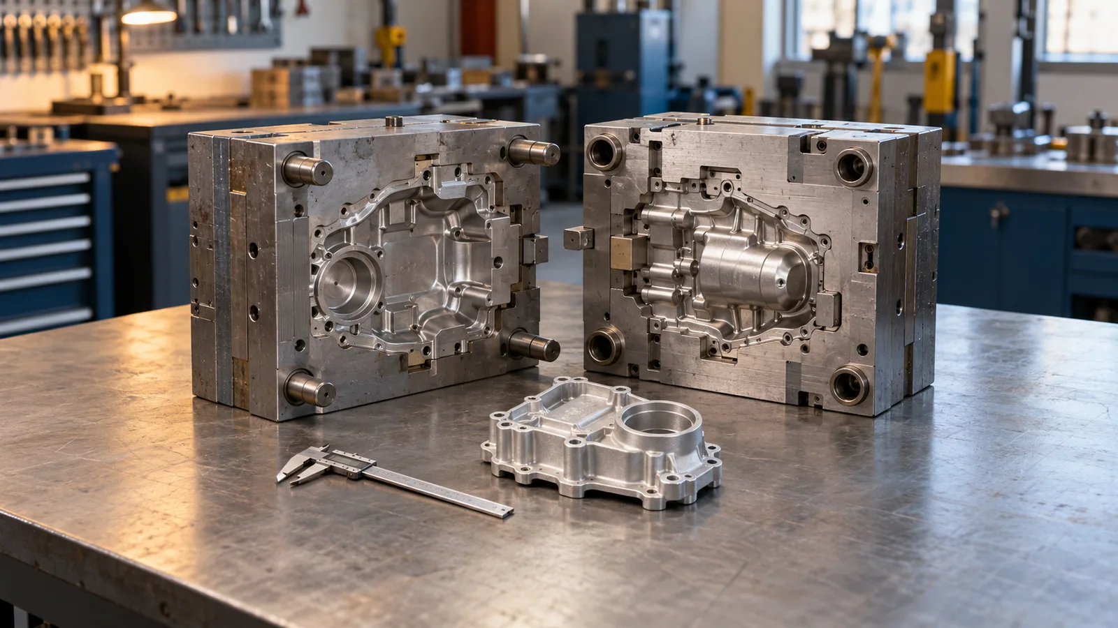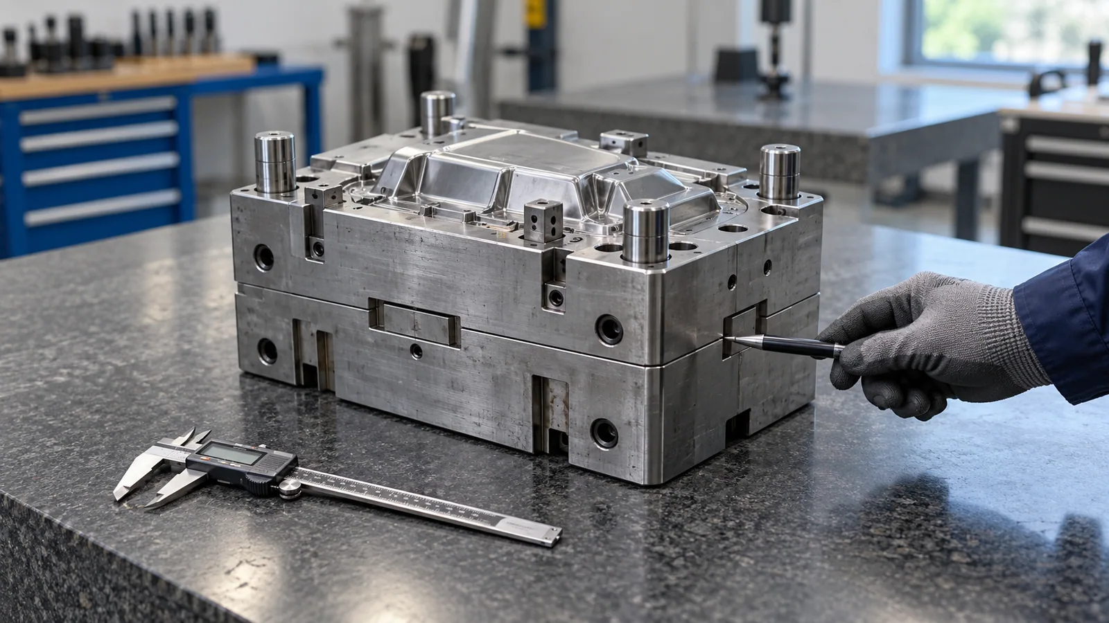
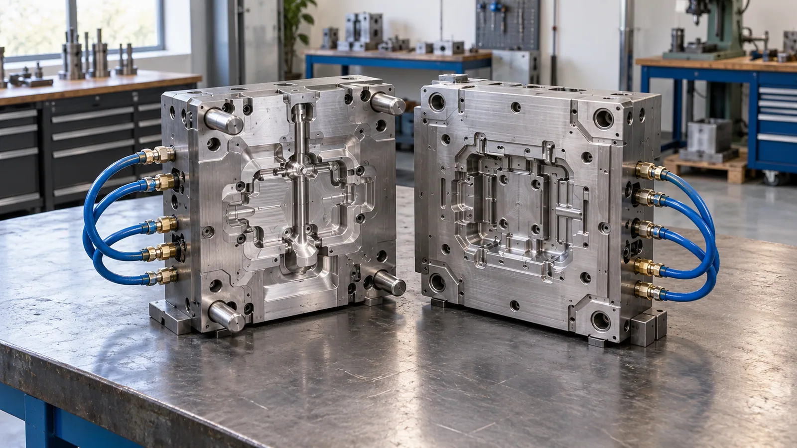
An aluminum die casting mold has three connected paths to manage: molten metal must enter the cavity, displaced air must escape, and heat must leave the working steel between shots. Gates, vents and temperature-control passages serve those paths, but they cannot be judged independently of the part shape, machine and process conditions. A gate drawing alone will not prove sound filling, and a surface defect alone will not identify the failed feature. The useful review is to follow an illustrative component from entry to last fill, then compare trial observations with the intended product requirements. NADCA: Die Design FAQ · NADCA: Gating and Process Planning Series
01 / 08
Begin at the gate, not the part outline
The runner leads liquid metal toward the part cavity. The gate is the controlled inlet connecting that path to the casting. Its location and section are chosen as part of a filling strategy, not merely because a convenient edge is available. The proposed layout affects where fronts travel, where they meet and where the gate connection must later be removed. NADCA's gating series treats machine constraints, runner design, overflows, vents and design verification together. NADCA: Gating and Process Planning Series
Picture an illustrative LED lighting housing: a broad shallow face, narrow ribs, a deeper mounting boss and an outer surface that remains visible after assembly. A gate on one edge might provide a plausible entry path, but the team still needs to consider how the metal reaches the distant ribs and how the resulting gate mark affects the visible edge. Moving the gate can change the fill pattern and the trimming location together. There is no position that is automatically best for every housing.
The buyer's contribution is to identify surfaces that must remain clean for appearance, sealing or assembly, and to distinguish as-cast from later finished requirements. The engineering team evaluates gate geometry and process conditions. A request to move a gate is therefore a design question, not a cosmetic note that can always be accepted without consequences.
ILLUSTRATIVE PATHS IN A DIE
02 / 08
Give displaced air somewhere to go
As metal enters, it pushes the air already in the cavity ahead of it. Vents provide a route out of the die. Overflow areas can receive metal at planned locations and can be connected to venting. NADCA's heat-sink case places overflow tabs opposite a gate and connects tabs by a vent line; that is one documented component-specific example, not a rule that overflows must always occupy that exact location. NADCA: Die Design FAQ · NADCA: Overflow Design Case
Review the expected last-to-fill regions of the illustrative lighting housing. If a narrow rib ends far from the gate, what route is planned for air displaced at that end? Where will an overflow attach, and can its removal be tolerated on the product? These are questions to ask while looking at the complete mold layout. A clean-looking cavity model that omits runners, vents and overflows does not answer them.
Air entrapment is one possible contributor to porosity, but a pore in a trial sample does not prove that a vent is missing. Entrained gas, metal condition, filling parameters, thermal behavior and geometry can interact. Diagnose the location, pattern and conditions of the observation before changing steel. NADCA discusses die design as a combination of metal flow, venting, cooling and ejection rather than a single isolated feature. NADCA: Die Design FAQ
| Observation | Possible line of investigation | What it does not prove |
|---|---|---|
| Incomplete feature near the far end of the flow path | Review fill progression, venting, temperature and local geometry | That enlarging one gate will solve it |
| Gas pores in a cut section | Review air escape, shot conditions, melt handling and the defect location | That every pore came from one missing vent |
| Gate mark on a functional face | Review gate and trimming location against the product drawing | That the entire mold is unusable |
| Variation near a heavy boss | Review local fill, heat removal, solidification and part geometry | That a cooling channel alone is the cause |
This table is a review aid, not a defect diagnosis. The project team needs actual sample evidence and process information to decide what changed and why.
03 / 08
Cooling is a die-system decision
Water or oil passages remove heat from die steel. Their location helps determine thermal balance, according to NADCA. A deeper boss, thin rib and large flat face do not impose the same local thermal demand. Temperature-control passages also have to fit around the cavity, supports, inserts, moving cores and other working features. NADCA: Die Design FAQ
Cooling matters to the whole sequence. Die temperature can influence how metal fills narrow regions, how the casting solidifies and how the component releases. An apparently simple proposal to move a channel may affect nearby steel strength or another feature. A sketch of evenly spaced drilled holes is therefore not evidence that a specific mold has a balanced thermal design.
The customer usually does not need to approve the route of every internal passage. Instead, flag product requirements sensitive to distortion, dimensions or surface appearance. If trial samples reveal a repeatable issue, the technical team can review it alongside measured conditions and the die design. Avoid promising a universal cycle time or defect-free casting based on a cooling diagram.
04 / 08
Illustrative example: reading one lighting-housing layout
Assume the housing above has a visible front face, a deep boss, two thin ribs and a side mounting ear. The following is a hypothetical review exercise, not a customer mold or a simulated filling result.
- Mark the product constraints. Identify the front face, mounting interfaces and any region requiring later finishing.
- Trace the proposed inlet. On the mold design, locate the runner, gate and trimming connection; check whether the gate mark falls on a protected surface.
- Trace the likely flow path. Ask the engineer which areas are expected to fill last and how the far rib and boss are reached.
- Trace the air exit. Look for the planned vents or overflow attachments at appropriate regions and check their removal locations.
- Review the thermal concept. Ask how the boss and thin areas are considered, while leaving channel sizing and process settings to the technical team.
- Compare the trial. Record where any incomplete feature, surface mark or dimensional issue appears, along with the sample revision and test condition.
The sequence does not imply that a customer can validate filling by eye. It provides a common map for discussing the proposed tool and for reporting observations clearly.
05 / 08
Why a trial sample is a checkpoint
The mold is trialed after manufacture. The resulting samples give the customer a physical part to test for fit and function, while the manufacturing team can examine the casting against the mold and process setup. A sample that looks acceptable in a photograph may still fail an assembly or sealing requirement. Conversely, a visible mark may be permissible if it sits on an agreed noncritical face. The product requirements determine the judgment. See Trial and Sample Approval.
If something is wrong, report more than “poor quality.” Identify the sample or drawing revision, the exact face or feature, the observed condition, and the test that revealed it. A marked photograph, measurement or mating-part description can help the team decide whether to review the gate, vent, thermal arrangement, product geometry or process conditions. It is important to separate the symptom from a proposed cause.
For EXACTMEC's mold-only projects, trial samples are sent to the customer for testing. The mold is dispatched after the customer confirms the samples meet the agreed requirements. This article explains the technical context of that checkpoint; it does not offer casting volume production.
06 / 08
Mistakes to catch before approving a layout
| Mistake | Why it creates risk | Better question |
|---|---|---|
| Reviewing only the cavity surface | The inlet and air-exit paths remain invisible | Can we see runner, gate, overflows and vents on the same layout? |
| Accepting a gate on a critical face without discussion | Removal may affect appearance or function | Which faces may show a gate or trim mark? |
| Treating a single pore as a complete diagnosis | Several material, process and tool factors can interact | Where is it, how repeatable is it, and under what trial conditions? |
| Copying cooling from a different component | Local geometry and moving parts differ | How is heat management addressed around this part's thick and thin regions? |
| Approving before resolving a product change | A revised mold could produce a part that no longer fits | Which drawing and 3D revision are we approving? |
07 / 08
Frequently asked questions
Is a larger gate always better for filling?
No. Gate design is part of an operating system involving the machine, runner and cavity. NADCA's gating series explicitly considers machine constraints and verification. Increasing one dimension without reviewing the rest is not a reliable rule. NADCA: Gating and Process Planning Series
Do overflows replace vents?
They can work together but are not interchangeable labels. An overflow provides a receiving area for metal at a planned location; vent passages provide an air exit. The exact connection is specific to the mold. NADCA: Overflow Design Case
Can a customer identify a cooling defect from one sample photo?
Usually not. A photo establishes what appears at a visible surface, not the complete cause. Provide the sample identification, location and test result so the technical team can evaluate thermal conditions alongside flow, geometry and process evidence.
08 / 08
What to review next
Before approving the mold design, identify protected product faces and the current drawing revision. Ask to see the metal entry, likely last-fill regions, air-exit features and temperature-control concept as one layout. After trial, compare identified samples with your functional requirements and send location-specific feedback. If you have a part drawing or physical sample for a new mold, start a mold inquiry.
Further reading
Technical references used to check this article:
Have a component in mind?
Share a clear 2D or 3D drawing, or tell us about a physical sample. We discuss the mold scope for your part.
Start a mold inquiry