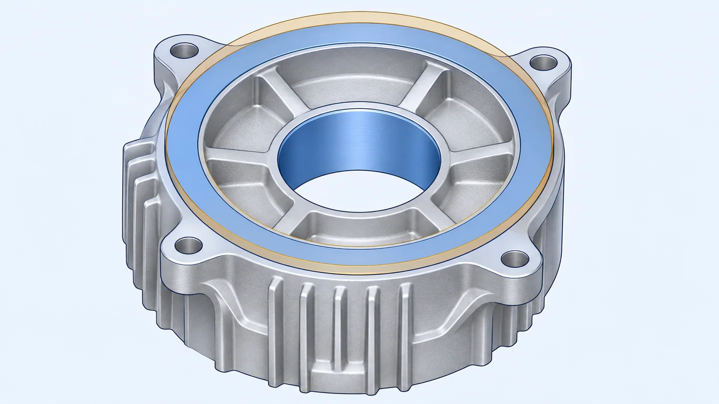
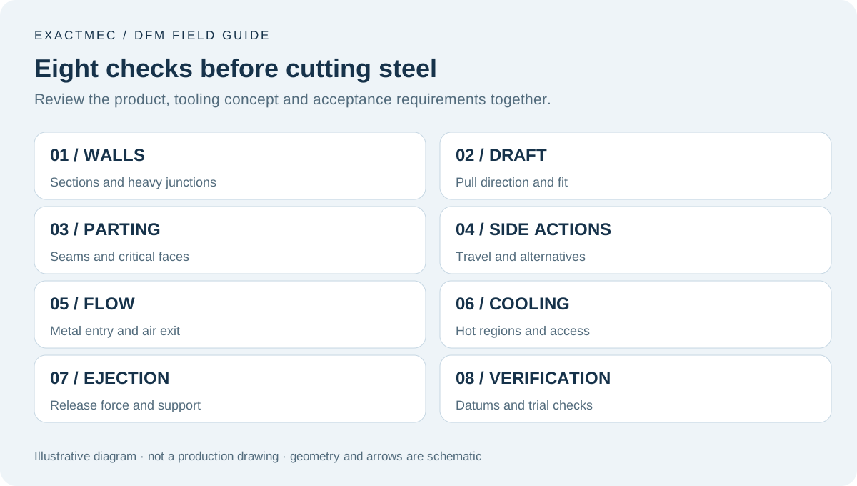
A useful design-for-manufacture review connects the component drawing to the way the die will fill, cool, open and eject. Before steel is cut, the product owner and project team should agree which features are functional requirements, which can change and which risks still need validation. This article sets out eight checks for aluminum high-pressure die casting molds. It is a review framework, not a mold design specification: suitable geometry depends on the alloy, machine, production conditions and acceptance requirements. A clean CAD model or a successful filling animation alone does not establish that a production tool is ready to manufacture.
01 / 08
Wall thickness: inspect intersections, not only nominal walls
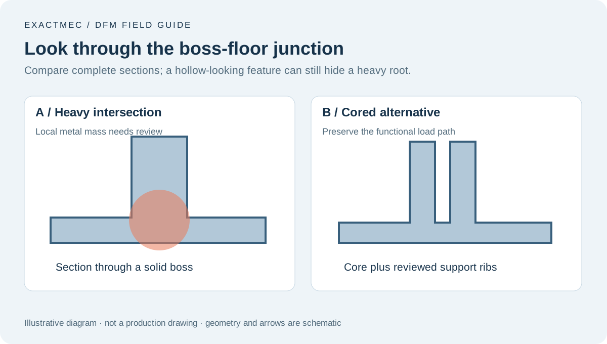
Start by sectioning the model through corners, mounting posts, flanges and rib junctions. A housing described as having uniform walls may still contain a large local mass where several features overlap. Different sections solidify at different rates; a thick junction can remain hot after the surrounding material has solidified, creating conditions that deserve review for shrinkage and distortion.
There is no universal minimum thickness that proves a part is suitable for die casting. NADCA's uniform-wall guidance recommends consistency and gradual transitions while recognizing that achievable sections depend on the process. Long flow paths, local loading and machining requirements may restrict how far a wall can be reduced.
Ask the team to mark the heavy junctions on actual section views. Where function permits, compare a cored boss, a redistributed rib or a gradual transition with the original solid feature. Do not remove material from a sealing land or fastener load path merely to make the thickness map look more uniform. Record which dimensions must remain unchanged and which proposed modifications require product approval.
Illustrative example: a small electronics enclosure
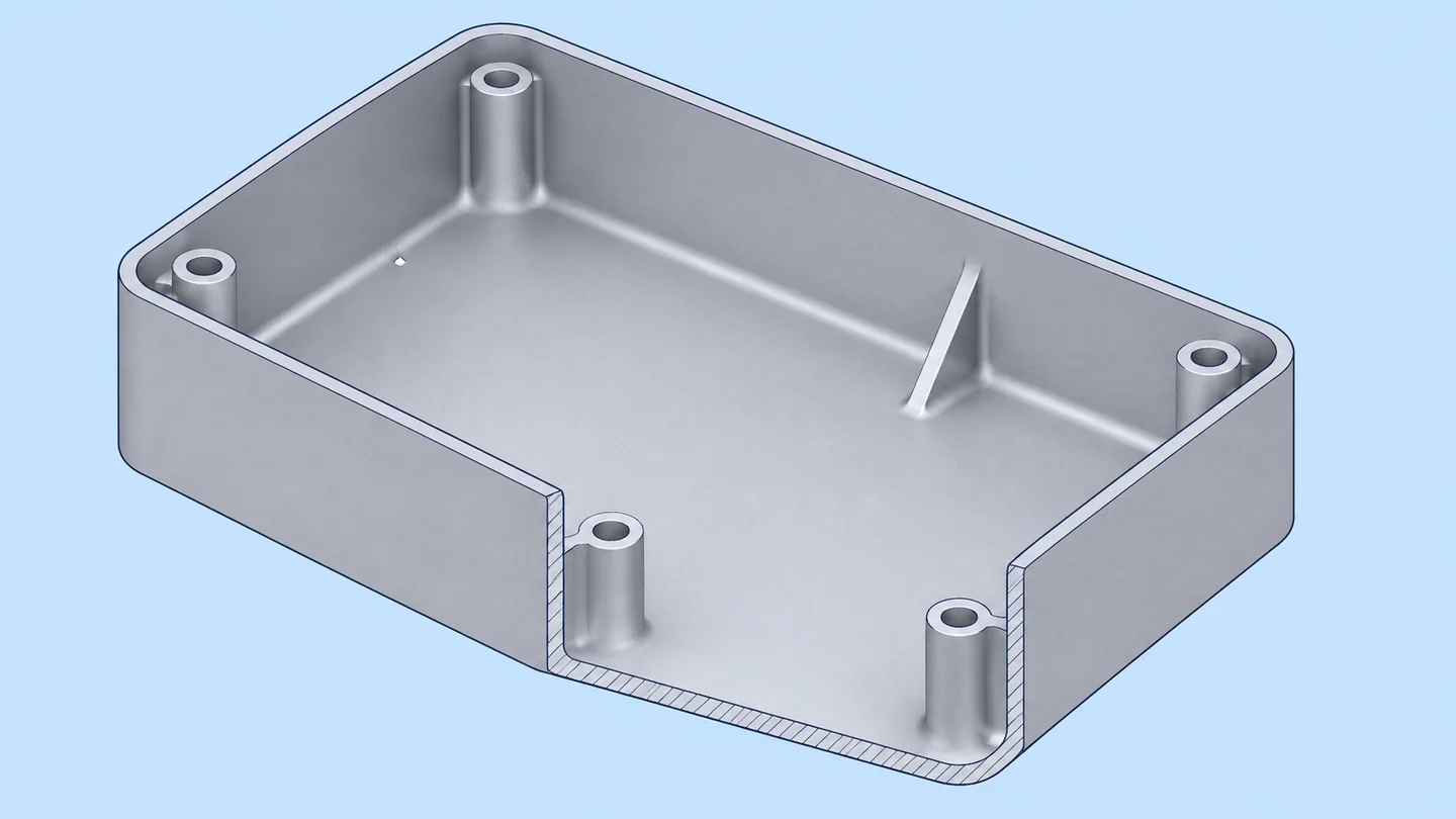
Consider a hypothetical enclosure with a sealing flange, four mounting bosses and a side connector opening. A solid boss merges into the floor at one corner. Coring the boss and revising the supporting rib may reduce the local mass, but the team must preserve screw engagement and the assembly load path. This is an illustrative example, not a customer case or evidence of measured improvement.
02 / 08
Draft: define the pull direction and the controlled section
Draft is the taper that helps a casting release from a cavity or core. The first review question is therefore directional: which steel surface forms this face, and in which direction does that steel withdraw? Check internal pockets, rib faces, boss bores and tall external walls against their actual release direction rather than applying one angle to the whole model.
NADCA's draft guidance explains that requirements vary with alloy, face type and feature depth. Internal and external features also behave differently as the casting cools around or away from the steel. A project-specific assessment is needed; an angle copied from another part is not a release strategy.
Draft changes the dimension along a feature's height. For a mating pocket, identify whether the functional size is specified at the opening, the base or another plane. For a sealing interface, distinguish the as-cast surface from a subsequently machined face. Document how draft, radii and tolerances are represented in the released drawing. A common mistake is approving a drafted model while retaining a drawing dimension that appears to demand the same width at every height.
03 / 08
Parting line: coordinate seams, trimming and dimensions
The parting line represents where the die halves meet. Its position affects more than appearance: it helps determine the tool arrangement, where metal and air paths can connect, and how trimming and dimensional control will be handled. NADCA's parting-line explanation discusses these linked decisions and the need for early cooperation between the part designer and die casting engineer.
Mark permitted seams, restricted cosmetic zones, sealing faces and accessible trimming edges on the component. Review whether a critical dimension is formed within one die half or crosses the split. Features crossing a parting line involve different sources of variation from features formed by a single insert; simply tightening the drawing tolerance does not remove that difference.
In the illustrative enclosure, a seam crossing the gasket land could affect the finishing plan. Moving the split might help that interface but complicate another feature or the release path. Compare complete alternatives rather than choosing a visually discreet seam in isolation. Obtain agreement on acceptable residual marks and the intended finishing operation before the split is treated as fixed.
04 / 08
Undercuts and side actions: compare casting with machining
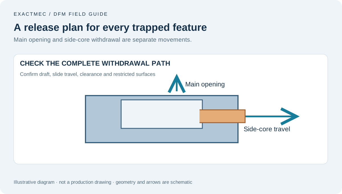
A side hole, hook or recessed connector feature may trap the part relative to the main opening direction. Identify each such feature and show the withdrawal path of the proposed moving core. Check travel, clearance, support and interference with other mechanisms. Customers need to understand the product consequences; detailed mechanism design remains the responsibility of the tooling team.
A slide is not automatically a mistake, and machining is not automatically cheaper. A side action adds moving interfaces and maintenance considerations, while machining adds a later operation, access needs, location requirements and material allowance. CWM's tooling overview provides background on production tooling and its component arrangements.
| Option for a side feature | Potential benefit | Questions to resolve |
|---|---|---|
| Cast with a moving core | Forms the feature during casting | Is there room for travel, support and maintenance? |
| Cast a pilot and machine later | Separates final accuracy from the cast opening | Are stock, cutting access and locating faces adequate? |
| Revise the product geometry | May remove a trapped feature | Does the revision preserve assembly and function? |
For the enclosure's connector opening, compare these options using expected production volume and the actual assembly requirement. Avoid approving a complex slide before checking whether a minor product revision would be acceptable. Equally, do not defer an inaccessible machining operation until after the tool is built.
05 / 08
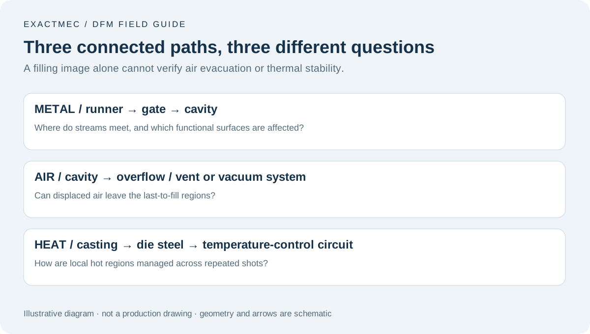
Gates, overflows and vents: review metal entry and air escape together
A gating concept must explain how metal reaches the component and how displaced air can leave. Ask for a review of likely last-to-fill regions, flow junctions, functional surfaces and trimming access. An attractive gate position is not useful if it sends an unfavorable flow path toward a critical face or leaves an isolated pocket with no effective air-exit strategy.
The NADCA tooling chapter hosted by CWM describes the relationship between gating, overflows, venting and vacuum. Vacuum can reduce entrapped air, but it is not a substitute for an appropriate component and tool design. Gas entrapment and solidification shrinkage also require different reasoning; a vacuum connection alone does not resolve every internal defect.
Where simulation is used, check the assumptions as carefully as the images: alloy, metal and die temperatures, shot conditions and air-boundary treatment. Ask what the result suggests, what was changed and what must still be checked during trials. Do not interpret a colored flow animation as a certified porosity map. Requirements for leak tightness, internal quality or machined sealing surfaces should be communicated before tool approval, with a suitable inspection method agreed for the project.
06 / 08
Cooling: inspect access to hot regions and the operating cycle
Temperature control is about managing the die's heat distribution across repeated shots. A water passage drawn near the cavity is only one part of that system. Review local steel thickness, hot features, available passage space, connections, sealing and access for cleaning. Also consider where moving cores, ejector pins and fasteners compete for the same space.
The project team should explain how its proposed layout addresses heavy junctions and narrow core regions without compromising tool integrity. A revised passage may improve access to one area while reducing the steel available elsewhere. More channels are not necessarily better when their placement, support or maintainability is unsuitable.
For the illustrative enclosure, the boss-floor junction and the surrounding thin panel need to be considered together. Before selecting an intervention, compare product coring, local cooling access and the intended casting cycle. During trials, distinguish start-up behavior from repeatable operating conditions. One acceptable sample taken from an unstable thermal cycle does not demonstrate a stable production window. See our gating, venting and cooling guide for the connected system view.
07 / 08
Ejection: support the part without compromising its function
Ejector pins apply force to release the solidified casting. Review pin contact regions, the surfaces that retain the casting and the direction in which the part can move. A thin panel or unsupported flange may need a different release arrangement from a stiff rib or reinforced junction. Ejection planning should follow the part's actual stiffness and release behavior.
Mark cosmetic, sealing and assembly faces where ejector marks are restricted. Then confirm that the remaining usable regions provide a practicable arrangement rather than moving all pins into a small convenient corner. Pin access and travel must also coexist with the cooling and core layout.
Dynacast's DFM discussion explains the purpose of draft, reinforced ejection contact areas and feature placement. In a project review, ask how the concept addresses a part that grips an internal core. Adding force without revisiting draft, surface condition or release balance can leave the underlying cause unresolved. The acceptable location and appearance of residual marks belong in the approval record, not only in a verbal discussion.
08 / 08
Tolerances and verification: agree what the trial must demonstrate
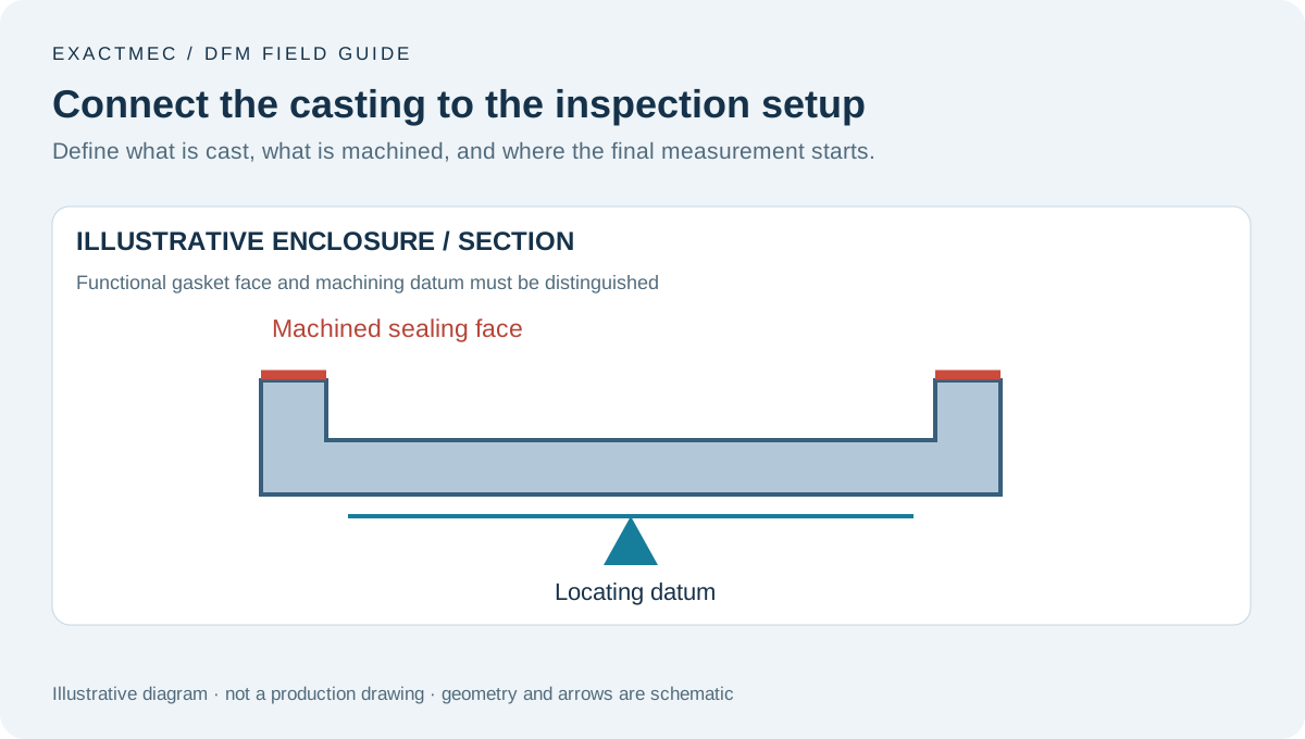
Separate as-cast requirements from dimensions achieved by machining. Identify the assembly datums, sealing interfaces, locating features and any features measured across moving tooling elements. Relate each important requirement to an inspection method and a defined part condition. A finished drawing should not leave the team guessing whether a dimension applies before or after machining or surface treatment.
For the enclosure, suppose the gasket face is machined while a mounting pocket remains as cast. The review should connect the machining setup to the casting's locating features, confirm adequate stock and define the final inspection reference. Inspection of an isolated sample without a consistent locating scheme can create disagreement even when both parties report plausible measurements.
| Review item | Evidence to agree before manufacture | What it does not establish |
|---|---|---|
| Revised part geometry | Identified drawing and model revision | That an unreviewed later change is acceptable |
| Tool concept | Split, release paths and functional interfaces | Final performance under every process condition |
| Simulation review | Assumptions, observations and planned actions | Guaranteed defect-free castings |
| Trial acceptance plan | Critical checks, sample condition and responsibilities | An automatic approval from one good-looking sample |
Close the review with a decision register
- Freeze the reference drawing and model revision used for the discussion.
- Mark functional, cosmetic, sealing and machining requirements on that revision.
- Record each proposed product change, its reason and the responsible approver.
- Assign unresolved tooling or process risks to an owner with a verification action.
- Confirm mold-design approval and the trial-sample acceptance steps before manufacture and handover.
An open issue is not necessarily a reason to abandon the project, but it must be visible and have an agreed path to resolution. For deeper dimensional planning, read tolerances, datums and machining; for release geometry, see parting lines, draft and undercuts.
EXACTMEC coordinates custom aluminum die casting mold projects with manufacturing partners in China. If you have a component to discuss, use the mold inquiry page and identify the drawing revision and critical requirements. Project-specific engineering decisions and deliverables are agreed during the project discussion.
Further reading
Technical references used to check this article:
Have a component in mind?
Share a clear 2D or 3D drawing, or tell us about a physical sample. We discuss the mold scope for your part.
Start a mold inquiry