Two suppliers can quote the same 3D model and still be working toward different finished requirements. One may assume a hole remains as-cast; another may include drilling and finishing. A sealing face may look flat in CAD while its flatness, reference setup and inspection stage are undefined.
Before tooling, connect each important dimension to the part's function, manufacturing stage and measurement method. This article uses a conceptual motor end housing to explain the discussion. It gives no universal tolerance or machining-stock value, and its illustrations are not production drawings.
01 / 08
Start with the assembly, then identify critical requirements
List the interfaces that control assembly and performance: a bearing seat, shaft opening, mounting face, bolt pattern or sealing land. Explain why each matters. A bore that locates a bearing has a different job from a clearance hole that simply allows a bolt to pass.
Separate size requirements from relationships between features. A diameter tolerance alone does not define the bore's location relative to the mounting face or its orientation. Flatness of one face is also different from its relationship to another face. Use appropriate drawing controls, with the applicable standard and edition stated, rather than expecting a general plus/minus note to express every requirement.
Do not tighten the entire drawing to make it appear precise. Assign requirements according to function, then review whether they can be achieved as-cast or need finishing. NADCA's product specification standards cover tolerancing and geometric dimensioning; project-specific application still needs agreement.
02 / 08
Choose datums that reflect how the part is located
A datum is an ideal reference established from a specified datum feature; it is not merely whichever edge is easiest to click in CAD. Decide which physical surfaces or features locate the part in assembly, machining and inspection, and whether those references are cast or machined.
For a motor housing, a mounting face might establish the primary reference, a bore axis might establish centering and another feature might control angular orientation. This is one possible concept, not a complete datum scheme. An engineer must choose the actual sequence and controls for the part's function.
Review how those references will be realized in a fixture. A rough, drafted or interrupted cast surface may not seat as assumed. If inspection and machining use different reference systems, document how results relate rather than treating the two setups as interchangeable.
Locate the part before measuring it
- 1Mounting reference
- 2Centering reference
- 3Angular orientation
03 / 08
Distinguish same-half and cross-parting dimensions
A dimension between features formed in one die half is not equivalent to a dimension crossing the parting surface. Die closure, the position of moving elements and other process effects can contribute differently. The casting's geometry, feature locations and relevant tolerance category all matter.
Identify which important features are formed by the same die half, opposite halves or moving cores. Discuss the proposed parting line before freezing the dimensional approach. Where function allows, changing the reference arrangement or feature layout may reduce unnecessary dependence on multiple tool elements.
Do not promise that a same-half dimension will automatically meet a specific tolerance. Ask the manufacturing team to review the actual size, alloy, tool design, process and agreed inspection method. Keep as-cast capability distinct from finished-machined capability in the quotation.
04 / 08
Define machining allowance before making the mold
Machining allowance is the planned material to remove between the casting surface and the finished surface. It is neither a general tolerance nor a shrinkage percentage. For an external face, the casting may retain material outside the finished boundary; for a bore, the cast opening may be smaller than the finished opening. The actual strategy depends on how the feature is made.
Too little stock can leave areas that do not clean up. Too much can add cutting time, change local sections and expose internal porosity. Review the allowance with the casting variation, locating method, distortion, cutting access and finished requirements in view. The CWM design and specification guide, particularly its machining-planning section, provides useful background.
Keep the casting and finished models distinguishable, with matching revisions and identified machined faces. A finished 3D model alone should not force the toolmaker to guess where stock belongs. Agree who defines the stock geometry and which version is used for tooling.
Separate casting and finished geometry
- 1Casting stock envelope
- 2Finished boundary
- 3Material to remove
05 / 08
Agree how and when the part will be measured
Write down the inspection state: as-cast, after trimming, after machining or after a specified surface treatment. Agree the reference setup, feature definition, suitable measurement method and any functional checks. A caliper reading and a fixture or coordinate measurement may answer different questions.
Also identify what the customer will test on trial samples. Assembly fit, a sealing function or bearing installation may need a check beyond a list of linear dimensions. Where a report, gauge or special test is required, include it in the agreed scope rather than assuming it comes with every mold order.
Coatings and finishing can affect the final interface. If a dimension applies after treatment, state that clearly and review it with the proposed process. Resolve inconsistent model and drawing instructions before approval.
06 / 08
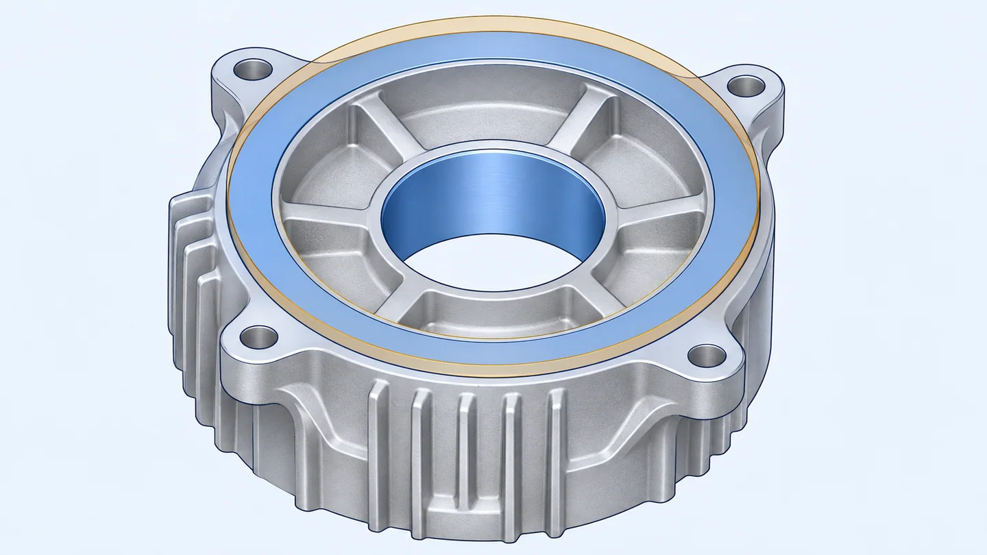
Worked example: a motor end housing
This conceptual example has a central bore, mounting flange and bolt pattern. It is not evidence of a completed customer project or a guaranteed process capability.
- Explain the interface. State whether the bore locates a bearing, guides another component or provides clearance.
- Identify reference features. Propose the functional mounting and centering references, then review how machining and inspection will locate the casting.
- Separate the two geometries. Mark the finished bore and flange, proposed cast stock and features that remain as-cast.
- Review tool-element relationships. Check whether critical features depend on a parting split or moving core, and assess the finishing route.
- Confirm sample acceptance. Agree the dimensional and functional checks before manufacturing, then test trial samples against that basis before mold handover.
This sequence makes quotations comparable by making assumptions visible. It does not require the customer to design the die's gating, cooling or mechanical construction.
07 / 08
A compact dimensional review checklist
| Item | What to specify | What to resolve before approval |
|---|---|---|
| Critical interfaces | Function, size and required relationships | Are the controls sufficient for assembly? |
| Datums | Named physical features and reference order | Can machining and inspection establish them consistently? |
| Manufacturing stage | As-cast versus finished requirements | Which operations and capabilities are being quoted? |
| Machining stock | Faces, bores and matching model revisions | Who defines the casting geometry and material to remove? |
| Acceptance | Inspection state, method and functional tests | What will be checked on trial samples, and by whom? |
Keep an open-issue list alongside the drawing revision. A tolerance copied from an unrelated component or an undefined “high precision” request is not an adequate acceptance criterion.
08 / 08
Frequently asked questions and next steps
Can every finished tolerance be achieved directly in the die?
No. Feasibility depends on the feature and process. Some interfaces may need machining or another agreed finishing operation. Review them individually instead of extending one capability claim to the whole part.
Does adding machining stock guarantee a clean finished surface?
No. Stock, casting variation, workholding and internal soundness must be reviewed together. The stock value alone does not establish the final result.
Should I send only the 3D model?
Include a clear drawing or notes identifying critical requirements, references, machining and revision, where available. Explain unresolved items. See our quotation preparation guide and wall, rib and boss review, then submit a mold inquiry.
EXACTMEC supplies custom aluminum die casting molds through coordinated manufacturing partners. Mold design is explicitly reviewed and approved after payment and before manufacturing; the customer tests and accepts trial samples before mold handover. Any machining, inspection or test deliverables must be agreed for the individual project.
Further reading
Technical references used to check this article:
Have a component in mind?
Share a clear 2D or 3D drawing, or tell us about a physical sample. We discuss the mold scope for your part.
Start a mold inquiry