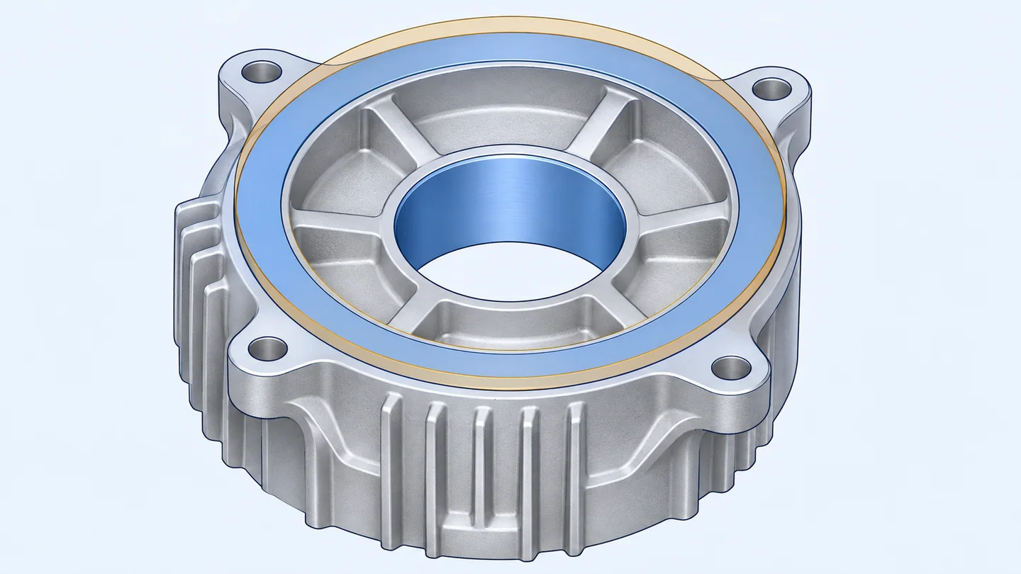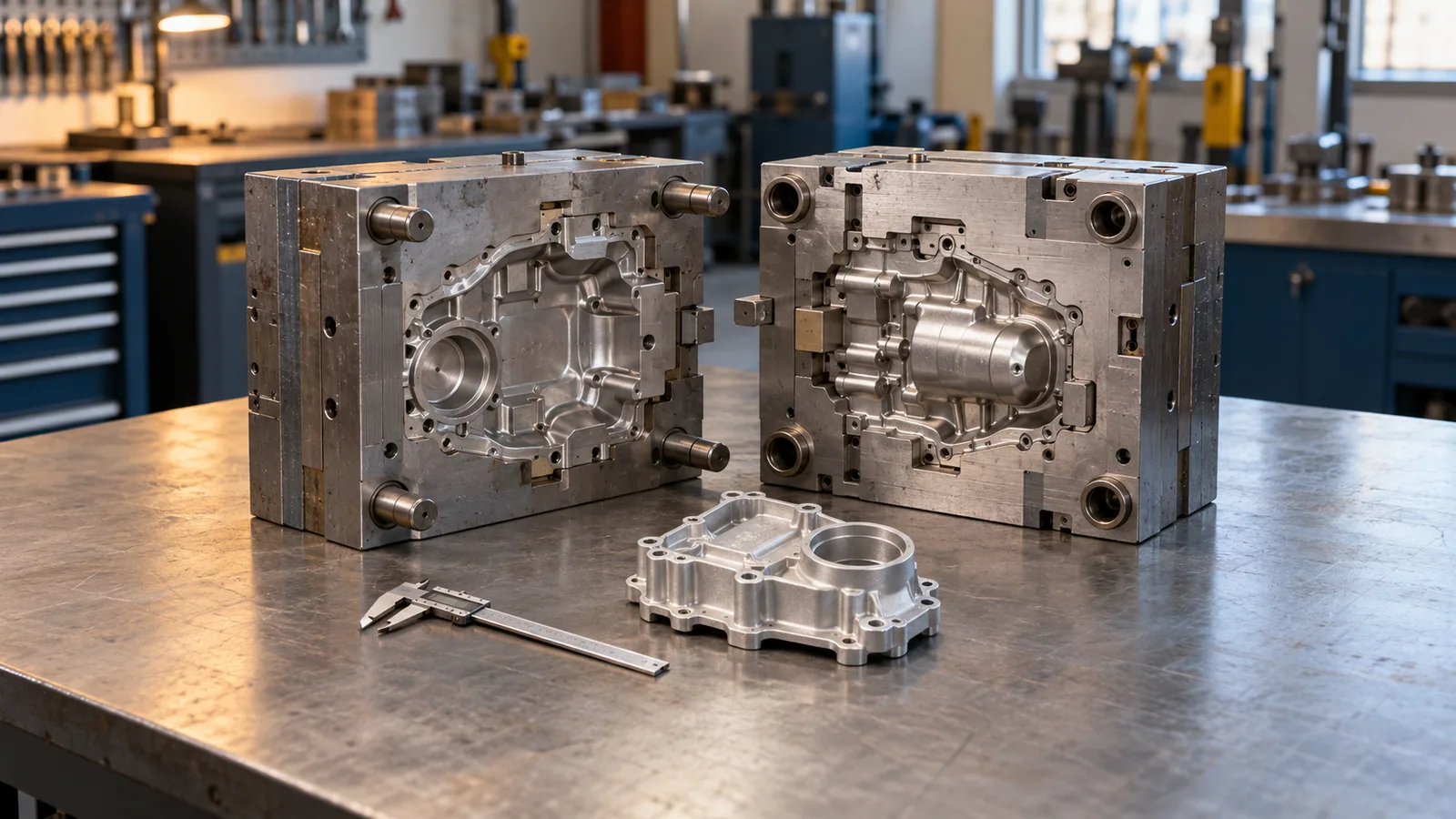
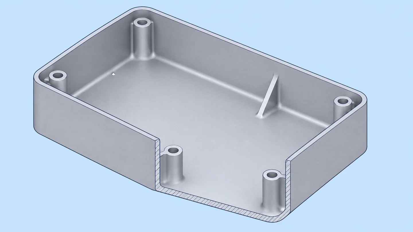
A housing can look uncomplicated from the outside while hiding difficult intersections inside. A thick screw post connected to a thin floor, or several ribs meeting at one corner, changes more than the weight of the part. It changes how metal reaches the feature, how heat leaves it and how the casting releases from the die.
This guide follows an illustrative electronics enclosure through a pre-tooling review. It explains what to flag on the product model before mold design is approved. It does not prescribe a universal minimum wall or rib-to-wall ratio: suitable dimensions depend on the alloy, flow distance, equipment, loads and actual die arrangement.
01 / 08
Start with wall continuity, not the smallest possible number
Nominal wall thickness is the starting section of the part, not a promise that every location is identical. Compare the floor, sidewalls, corners, flanges and transitions. Abruptly joining a thin panel to a large solid mass creates a local thermal imbalance; the heavier region can cool differently and deserves review for shrinkage-related defects and distortion.
The answer is not automatically to thin everything. A long flow path or a heavily loaded mounting area may need a different solution. Review the wall map with the die caster, including the metal-entry route, venting and temperature control. NADCA's uniform-wall guidance provides the underlying design principle, rather than one number that fits every enclosure.
Use section views through the thickest junctions. Where function permits, investigate coring out excess metal and providing a gradual transition. Retain material needed for sealing, fastener loads and planned machining. Changes to the product geometry require the product owner's approval.
Read the wall section
Abrupt heavy junction
More continuous section
02 / 08
Add ribs along a useful load path
A rib is a stiffening feature, not a decorative line. Ask what it connects and what movement it restrains: for example, a mounting boss to an adjacent wall, or a wide floor against bending. A taller or thicker rib is not automatically better if it creates a heavy intersection, obstructs another feature or becomes difficult to fill and release.
Check the rib root, its intersection with other ribs and the space between nearby features. Add suitable root radii and release draft, then review the resulting local section. A generous-looking radius can itself add a substantial volume of metal at a crowded junction. The geometry must also leave workable die steel and access for finishing or machining where required.
Do not import a plastic-molding rib percentage as an aluminum die-casting rule. NADCA's rib guidance describes their role in stiffness and metal flow; the actual thickness, height and spacing need a part-specific review.
Inspect the whole connection
Hollow mounting boss
Rib and root transition
03 / 08
Review mounting bosses as hollow, loaded features
A mounting boss is the raised feature around a fixing location. Its outside diameter alone says little about its manufacturability. Section through the boss and its base: a hollow post can still create a thick mass where it merges into the floor or wall. Consider the complete material junction, not only the central hole.
Define the fastener type, engagement, assembly load and whether the hole will be cast, drilled, tapped or otherwise finished. These choices affect the cored opening, machining access and the material that must remain. A cast pilot hole is not equivalent to a finished threaded connection.
Boss inner and outer faces need a release strategy, and supporting ribs need usable transitions. Avoid putting a boss so close to a wall that the intervening tool steel becomes an unreviewed constraint. See NADCA's boss design guidance for the relationship between coring, ribs, fillets and draft.
04 / 08
Check release, clearance and machining together
A structurally sensible feature may still block the opening direction. Review rib faces and boss bores against the intended pull direction; side features may require moving cores or subsequent machining. Draft changes the section along its height, so identify where the functional thickness or fit is controlled.
Check clearance for a screwdriver, tapping tool, fixture and mating component. Keep critical sealing lands and functional contact faces identifiable. If a face is to be machined, distinguish the finished geometry from the casting stock before changing nearby ribs or bosses. Our parting-line and draft article explains the release review in more detail.
05 / 08
Worked example: an electronics enclosure
Consider a conceptual enclosure with four fixing posts, a flat cover interface and two internal ribs. This is a teaching example, not a completed customer project or a validated casting design.
- Mark the fixed interfaces. Identify the cover seal, PCB clearances and screw locations before proposing geometry changes.
- Section the post bases. Check whether each post adds an unnecessary solid mass to the floor. Explore coring and smoother transitions without reducing the required fastener support.
- Trace the rib loads. Retain ribs that support the intended load path; investigate intersections that collect material without a clear purpose.
- Check the manufacturing routes. Review filling, release, tool access and the proposed finishing of the fixing holes together.
- Record the agreed revision. The reviewed model, dimensions and open questions must refer to the same product version before mold design approval.
A lighter model is not automatically the better result. The useful result is a geometry whose functional requirements and proposed manufacturing approach have been reviewed together.
06 / 08
What to include in the review package
| Area | Information to mark | Decision to confirm |
|---|---|---|
| Walls and transitions | Sections through thin panels and heavy junctions | Which geometry can change without affecting function? |
| Ribs | Load direction, clearances and intersecting features | Does each rib provide useful support and allow release? |
| Bosses | Fastener, hole finish and assembly requirements | What is cast, what is machined, and what material must remain? |
| Functional faces | Sealing, locating and contact surfaces | Which faces and dimensions take priority? |
| Product revision | Matching 3D model, 2D drawing and change notes | Which version is the quotation and design-review basis? |
Mark unresolved items explicitly instead of silently replacing them with generic dimensions. A simulation or engineering review may help evaluate a proposal, but a polished CAD image alone does not establish casting quality or structural adequacy.
07 / 08
Frequently asked questions
Is there one recommended wall thickness for all aluminum housings?
No. Overall size, alloy, filling distance, geometry and performance requirements affect the feasible section. Use a supplier-reviewed proposal for the actual part rather than a number detached from its manufacturing conditions.
Can ribs always replace a thicker wall?
No. Ribs can improve stiffness in useful directions, but they do not automatically satisfy sealing, impact, fatigue or fastener requirements. The product's load cases and the casting design must be considered together.
Does coring a boss mean its hole needs no machining?
No. The final size, thread, position and surface condition may require secondary work. Specify the finished requirement and agree the casting and machining approach before tooling.
08 / 08
Turn review notes into a clear mold inquiry
Share a clear 2D or 3D product drawing, or describe an assessable physical sample, together with the critical interfaces and the current revision. Our quotation preparation guide explains the useful starting information; the dimensions and machining article covers how to define the finished requirements.
EXACTMEC supplies custom aluminum die casting molds and coordinates with manufacturing partners in China. After payment, the mold design is reviewed and explicitly approved before manufacturing. Trial samples are then tested and accepted by the customer before mold handover. Start a mold inquiry to discuss the scope for your component.
Further reading
Technical references used to check this article:
Have a component in mind?
Share a clear 2D or 3D drawing, or tell us about a physical sample. We discuss the mold scope for your part.
Start a mold inquiry